3 About Lead Free Solder (PbF)
Note: Lead is listed as (Pb) in the periodic table of elements.
In the information below, Pb will refer to Lead Solder and PbF will refer to Lead Free Solder.
The Lead Free Solder (PbF) used in our manufacturing process and discussed below is (Sn+Ag+Cu). Those are Tin (Sn), Silver (Ag) and Copper (Cu), although other types are available.
This model uses PbF in its manufacture due to environmental conservation issues. For service and repair work, we would suggest the use of PbF as well, although Pb may be used.
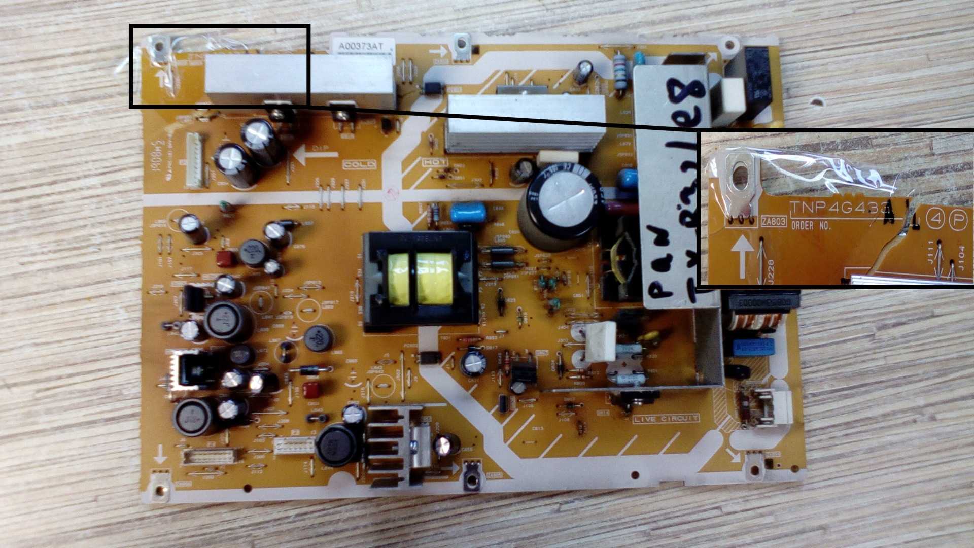
PCBs manufactured using lead-free will have the “PbF within a leaf Symbol” stamped on their back.
Caution
•PbF has a higher melting point than that of standard solder. Typically the melting point is 50 ~ 70°F (30~40°C) higher. Please use a high temperature soldering iron and set it to 700 20°F (370 10°C).
•PbF will tend to splash when heated too high (about 1100°F or 600°C).
If you must use Pb solder, please completely remove all of the PbF on the pins or solder area before applying Pb. If this is not practical, be sure to heat the PbF until it melts, before applying Pb.
•After applying PbF to double layered boards, please check the component side for excess solder which may flow onto the opposite side (see Figure 2).
Figure 2
Suggested PbF
There are several kinds of PbF available for purchase. This product uses Sn+Ag+Cu (tin, silver, copper) solder. However, Sn+Cu (tin, copper) and Sn+Zn+Bi (tin, zinc, bismuth) solders can also be used.

1 Safety Precautions
1.1. General Guidelines
1. When servicing, observe the original lead dress. If a short circuit is found, replace all parts which have been overheated or damaged by the short circuit.
2. After servicing, see to it that all the protective devices such as insulation barriers, insulation papers shields are properly installed.
3. After servicing, make the following leakage current checks to prevent the customer from being exposed to shock hazards.
1.2. Touch-Current Check
1.Plug the AC cord directly into the AC outlet. Do not use an isolation transformer for this check.
2.Connect a measuring network for touch currents between each exposed metallic part on the set and a good earth ground such as a water pipe as shown in Figure 1.
3.Use the Leakage Current Tester (Simpson 228 or equivalent) to measure the potential across the measuring network.
4.Check each exposed metallic part and measure the voltage at each point.
5.The potential at any point (touch current) expressed as voltage U1 and U2, do not exceed the following values: For AC: U1 = 35 V (peak) and U2 = 0.35 V (peak);
For DC: U1 = 1.0 V,
NOTE :
The limit value of U2 = 0.35 V (peak) for AC and U1 = 1.0 V for DC correspond to the values 0.7 mA (peak) AC and 2.0 mA DC. The limit value U1 = 35 V (peak) for AC correspond to the value 70 mA (peak) AC for frequencies greater than 100 kHz.

8 Service Mode Adjustment
Set channel 99, then set the timer to 30 min. Press the “RECALL” button on the remote control and the “-” button on the LCD panel.
8.1.SERVICE 1
1. Press the red button (on the remote control) for adjustment below.
8.2.SERVICE 2
1. Select CEC CHECK mode in service 1, then press the “HOLD” button (on the remote control) to enter service 2.
8.3.Self Check Mode
1.Press the “TIMER” button (on the remote control) and the “DOWN” button on the LCD panel.
2.Press the “NORMALIZE” button (on the remote control) to Exit.
8.4.Hotel Mode Adjustment
1.Press the “VOLUME DOWN” button on the TV panel while pressing the “TV/AV” button on the remote control.
2.Press the “MENU” button on the remote control to Exit the Hotel Mode Function.